TurboLamik is one of the most popular standalone controllers for the ZF 8HP automatic transmission, and pairing one with a 6.2-liter supercharged Hellcat engine makes for an exceptionally capable drivetrain. But the transmission needs far more than a simple tachometer signal to shift correctly. As an 8HP transmission controller, the TurboLamik needs fast, accurate data — engine speed, load, calculated torque, throttle position, brake status, and torque-reduction events during shifts.
When the factory Hellcat PCM stays in place, much of that may arrive over the CAN bus. When CAN data is unavailable or incomplete, dedicated engine-speed and manifold-pressure sensors fill the gap. This guide covers the options and the specific sensors we recommend for a Hellcat and ZF 8HP build.

The Best Option: Use the Factory Hellcat PCM Over CAN
Before adding sensors, determine whether the TurboLamik can receive valid engine information from the factory Hellcat PCM. CAN communication is generally preferred because it can provide more than RPM — depending on PCM calibration and TurboLamik profile, the controller may receive engine RPM, throttle and accelerator-pedal position, calculated torque, brake-switch status, engine state, and torque-management data.
For a factory-PCM installation, the Dodge 8HP CAN profile should be the first configuration tested. The important word is tested. A modified PCM calibration may report torque differently — limited, rescaled, or no longer representative of the engine's actual output. That matters because a Hellcat can produce enough torque to damage an improperly configured transmission quickly. Confirm that RPM, throttle, and torque values are realistic in the TurboLamik's live data before driving under load. If accurate RPM and torque are available over CAN, there is usually no reason to add a crank sensor or MAP sensor solely for the transmission controller.
If the CAN stream is the problem rather than the sensors — slow updates, missing torque, or no-communication faults — diagnosing it at the signal level comes first. (See our guide on diagnosing CAN bus faults before replacing a module.)
When Dedicated Sensors Are Needed
Dedicated sensors become useful when:
- The factory Hellcat PCM is not being used
- An aftermarket ECU has no supported CAN profile
- The CAN stream contains no valid torque information
- Engine-speed data over CAN updates too slowly
- A completely isolated transmission-control system is preferred
- The factory crank signal should not be shared with another device
In this arrangement the TurboLamik needs two primary inputs: a high-resolution engine-speed signal and a manifold absolute pressure (MAP) signal for estimating load and torque. For a Hellcat build, we recommend a dedicated Hall-effect crank sensor paired with an appropriately sized MAP sensor.
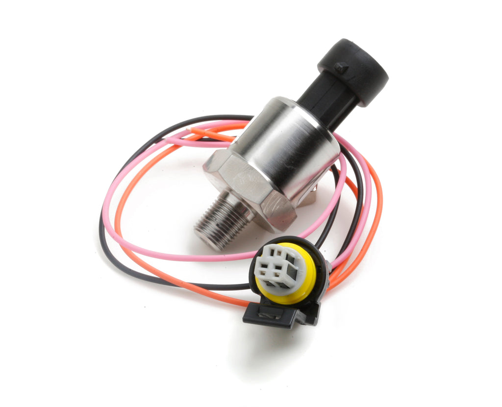
Recommended Engine-Speed Sensor: ZF/Cherry GS100502
Our preferred dedicated engine-speed sensor is the ZF/Cherry GS100502 Hall-effect gear-tooth sensor (datasheet & distributors). It detects ferrous-metal targets and is well suited to reading a crank-mounted trigger wheel, producing the fast, repeatable signal a transmission controller needs. Key characteristics: M12×1 threaded body, adjustable gap, near-zero-speed detection, high-frequency capability (to 15 kHz), automotive temperature range, sealed construction, flying-lead wiring, and open-collector output. The threaded body makes it easy to set and hold the correct air gap to the trigger wheel.

Why a Hall-Effect Sensor Is Preferred
A variable-reluctance sensor can produce a usable crank signal, but its output voltage changes with engine speed — weak during cranking, much stronger at high RPM. A Hall-effect sensor produces a consistent digital signal across the range, which makes threshold configuration easier and reduces unstable RPM readings at low speed. For a standalone transmission controller, a clean square wave beats a speed-dependent analog waveform.
Recommended Trigger Wheel: 60-2

Pair the sensor with a rigid, ferrous-steel 60-2 crank trigger wheel. A 60-2 wheel has 60 possible tooth positions with two removed, so the sensor sees 58 physical teeth per crankshaft revolution — far better resolution than a tachometer output's few pulses per rev. That resolution helps the controller evaluate engine acceleration, torque-converter slip, shift timing, clutch synchronization, and speed changes during gear engagement. For a 60-2 wheel, the TurboLamik is generally configured initially for 58 detected teeth; exact terminology varies by firmware, so check current TurboLamik documentation during setup.
Wiring the GS100502
The GS100502 uses an open-collector output — it pulls the signal toward ground but needs an external pull-up resistor to create the high portion of the waveform. A typical configuration:
| Connection | Recommended configuration |
|---|---|
| Sensor supply | Regulated 5 V |
| Sensor ground | Shared sensor ground |
| Sensor signal | TurboLamik engine-speed input |
| Pull-up resistor | ~1 kΩ between signal and 5 V |
| Wiring | Shielded automotive cable |
| Initial sensor gap | ~1.0–1.5 mm |
Confirm the actual air gap from the trigger-wheel material, tooth geometry, and sensor specs. Then check the signal with an oscilloscope at the TurboLamik connector — testing at the controller confirms the whole wiring run is clean, not just the sensor output.
Alternative: Use the Factory Hellcat Crank Signal
The factory Hellcat crank signal may also be usable. The late Gen III Hemi uses a high-resolution crank pattern (commonly described as 58-tooth), which in principle provides the resolution the TurboLamik needs. But the factory crank circuit is critical to engine operation — loading or distorting it can cause misfires, loss of sync, no-start, intermittent stalling, trouble codes, or shutdown at high RPM. Do not connect it directly to another controller until its electrical characteristics are verified: signal-high and -low voltage, output type, whether it is actively driven or open-collector, and whether the waveform stays stable when another device is connected, during cranking, and at maximum RPM. When sharing the factory signal, a high-impedance buffer or signal conditioner is the safer approach. For a new install, a dedicated sensor and trigger wheel give better electrical isolation.
Recommended MAP Sensor
Engine RPM alone can't tell the controller how much torque the engine is making. When reliable torque is not available over CAN, the TurboLamik can estimate it from engine speed and manifold absolute pressure — which requires a properly scaled MAP sensor and a carefully configured torque table.
AEM 30-2130-50 (3.5-Bar) for Most Builds
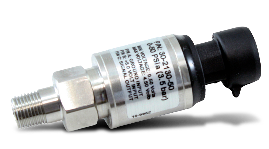
For a stock or moderately modified Hellcat, our preferred MAP sensor is the AEM 30-2130-50 3.5-bar absolute-pressure sensor: ~50 PSIa range, 0.5–4.5 V output, regulated 5 V supply, fast response, stainless construction, 1/8-inch NPT. Because it's an absolute sensor, its range includes atmospheric pressure (~14.7 psi at sea level), so a 50 PSIa sensor gives usable boost measurement into roughly the mid-30-psi range — substantial headroom for a stock or moderately upgraded Hellcat without sacrificing as much resolution as a 5-bar sensor.
When to Use a 5-Bar MAP Sensor
A 5-bar MAP sensor is more appropriate above roughly 30–35 psi of boost. Suitable options include the AEM 30-2130-75 and the Holley 554-108. A 5-bar sensor adds pressure range but spreads it across the same 0.5–4.5 V window, so each volt represents a larger pressure change — less resolution than a 3.5-bar sensor. Size the sensor for the engine's actual boost range rather than reaching for the biggest one automatically.
| Engine configuration | Suggested MAP range |
|---|---|
| Factory or lightly modified Hellcat | 3.5 bar |
| Moderate pulley/boost upgrades | 3.5 bar, if adequate headroom remains |
| High-boost race build | 5 bar |
| Unknown future boost plans | 5 bar (reduced resolution accepted) |
MAP Sensor Wiring
| MAP sensor wire | Connection |
|---|---|
| 5 V supply | TurboLamik regulated 5 V |
| Sensor ground | TurboLamik sensor ground |
| Analog signal | TurboLamik MAP input |
Use the controller's sensor ground — grounding elsewhere can introduce voltage offsets in a high-current drivetrain. Verify the MAP signal in live data at key-on/engine-off, idle, light vacuum, atmospheric, moderate boost, and maximum expected boost. Key-on/engine-off should read close to local atmospheric pressure, not zero, unless the software displays gauge rather than absolute pressure.
Building the Torque Model
Once RPM and MAP are available, the controller still needs a realistic relationship between those inputs and engine torque. A supercharged Hellcat doesn't make the same torque at every RPM for a given MAP value — airflow, ignition timing, bypass-valve position, supercharger efficiency, exhaust flow, and calibration all matter. Build the torque table from engine- or chassis-dyno data, ECU logs, known torque calculations, or conservative initial estimates followed by controlled validation. Do not populate it with peak advertised torque across the whole operating range. An inaccurate model can command too little clutch pressure; under Hellcat torque, insufficient pressure is the more immediate durability concern. Begin conservatively, monitor clutch behavior, and validate under progressively increasing load.
Sensors and Signals to Avoid
Not every RPM signal is suitable for transmission control. Avoid a dashboard or low-resolution tach output, coil-negative, a camshaft-position signal, a heavily filtered ECU tach signal, a slow CAN-to-analog converter, an unverified factory crank-sensor splice, and inductive pickups intended only for a display gauge. These may look accurate on a tachometer while being too slow or too coarse for converter-slip and clutch-speed calculations. A dash tach only needs to show an approximate engine speed; a transmission controller needs to detect rapid changes during shifts and converter operation. Very different requirements.
Recommended Hellcat Sensor Package
For a Hellcat install where usable engine information is not available over CAN, our preferred package:
- Engine speed: ZF/Cherry GS100502 Hall-effect sensor, rigid 60-2 ferrous-steel trigger wheel, adjustable bracket, regulated 5 V supply, ~1 kΩ pull-up, shielded wiring, oscilloscope validation at the controller.
- Engine load: AEM 30-2130-50 3.5-bar MAP for most street/moderately modified builds; AEM 30-2130-75 or Holley 554-108 5-bar for high-boost; regulated 5 V supply, dedicated sensor ground, short stable manifold connection.
- Controller config: high-resolution engine-speed input, tooth count for the 60-2 wheel, threshold from measured voltage, MAP calibration from the sensor data, conservative RPM/MAP torque table, live-data validation before driving, progressive load testing before full power.
Final Recommendation
The order of preference for a Hellcat and TurboLamik-controlled ZF 8HP:
- Use accurate RPM and torque from the factory PCM over CAN.
- Use an aftermarket ECU with supported CAN communication.
- Use a dedicated Hall-effect crank sensor and MAP sensor.
- Share the factory crank signal only through a verified, high-impedance interface or signal conditioner.
For a dedicated sensor install, the ZF/Cherry GS100502 with a 60-2 trigger wheel and an AEM 3.5-bar MAP sensor is a strong starting combination; reserve the 5-bar MAP for engines that genuinely need the range. The transmission controller needs accurate, fast, electrically stable information — a Hellcat leaves very little margin for an unreliable RPM signal or an unrealistic torque model. This is exactly the kind of cross-platform integration work we engineer every day.
Frequently Asked Questions
Does a TurboLamik need a separate crank sensor?
Not always. If the factory PCM (or a supported aftermarket ECU) provides accurate, fast RPM and torque over CAN, you usually don't need a dedicated crank sensor. Add one when CAN data is missing, slow, or unreliable, or when you want a fully isolated transmission-control system.
What MAP sensor should I use for a Hellcat with a TurboLamik?
For a stock or moderately modified Hellcat, a 3.5-bar sensor like the AEM 30-2130-50 gives the best resolution with enough boost headroom. Move to a 5-bar (AEM 30-2130-75 or Holley 554-108) only when boost will exceed roughly 30–35 psi.
What trigger wheel works with the GS100502?
A rigid, ferrous-steel 60-2 wheel (58 teeth, two missing). It gives the high resolution the controller needs for converter-slip and clutch-speed calculations; initialize the TurboLamik for ~58 teeth per revolution and confirm against current firmware docs.
Can I use the factory Hellcat crank signal for the transmission controller?
Only through a verified high-impedance buffer or signal conditioner. The factory crank circuit is critical to engine operation, and loading it directly can cause misfires, no-start, or high-RPM shutdown. A dedicated sensor is the safer choice for a new install.
Latimer Technologies builds, repairs, and engineers automotive electronics — mail-in, nationwide. If you're integrating a TurboLamik 8HP into a Hellcat or any platform and want the sensors, wiring, and torque model done right, send us the details.
Got a module that won't cooperate?
Mail-in diagnostics, reflashing, restoration, and custom engineering — nationwide, with a signed report on every job.