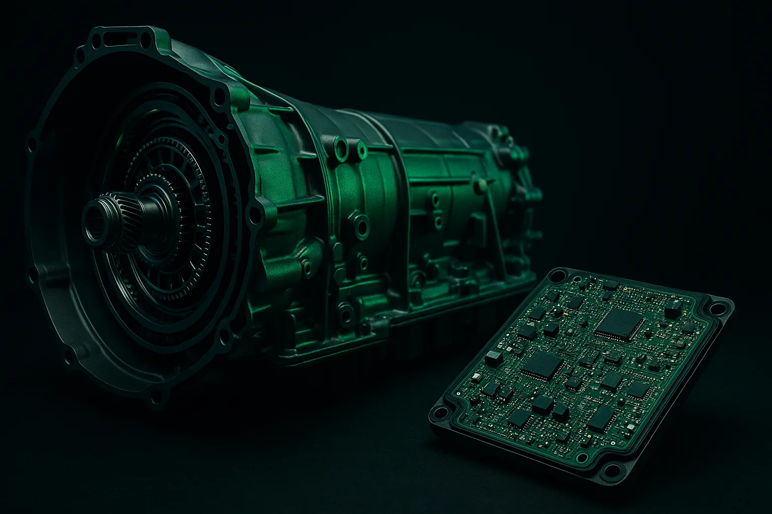
The ZF 8HP is arguably the best automatic transmission ever dropped behind an LS engine — eight well-spaced ratios, a sub-150-millisecond shift time, and a torque capacity that laughs at anything short of a built drag engine. The obstacle has always been control: the 8HP was designed around BMW's proprietary CAN architecture, and for years that meant sourcing a donor module, reverse-engineering CAN frames, or accepting an awkward middleware solution. The Turbolamik TCU eliminates that problem entirely. It replaces the factory ZF circuit board at the PCB level, routes every internal solenoid and sensor wire directly to an external controller, and gives you a clean, documented harness interface that works equally well with a CAN-capable standalone ECU or a fully analog input set — including carbureted builds where there is no CAN bus at all.
This guide walks through the complete wiring sequence for an LS + ZF 8HP Turbolamik build from first wire to first drive. It covers constant-power and ground routing, engine-speed signal conditioning for both Gen III 24x and Gen IV 58x LS sensors, the TPS and MAP discrete path, shifter and paddle wiring, torque-reduction output, the CAN path for compatible ECUs, and the transbrake option for 8HP90/95 race builds. A commissioning checklist and an FAQ section address the questions that most commonly surface during installation. Pin numbers throughout refer to the Turbolamik 2.0 official wiring manual.
Why the Turbolamik Is the Right TCU for an LS Swap
Most CAN-overlay solutions for the ZF 8HP still depend on at least some factory ZF software running somewhere on the bus. The Turbolamik takes a fundamentally different approach: the factory TCU board is physically removed and a custom PCB is soldered directly into the mechatronics unit. Every solenoid, pressure sensor, speed sensor, and temperature sensor inside the transmission then connects to the external Turbolamik controller box through a single harness rather than through BMW firmware. The result is a transmission controller that has zero dependency on OEM CAN messages.
For LS swaps, this matters in three concrete ways. First, you are not forced to emulate BMW gear-selector CAN traffic — you can use a Turbolamik PCD push-button display, an OEM electronic shifter on CAN1, or simple momentary buttons wired directly to AUX inputs. Second, the controller accepts engine speed, TPS, and MAP as plain 0–5V analog signals when CAN is not available, so a carbureted LS or an LS running Megasquirt without a CAN output is fully supported under Profile 0. Third, when you do have a CAN-capable ECU (Holley Dominator, Haltech Elite, MaxxECU, Link, AEM Infinity, Motec, ECUMasters EMU Black, and others), the TCU reads RPM, load, and calculated torque directly off the bus and can issue a CAN-based torque reduction command back — no extra wires needed for those signals.
Hardware Prerequisites Before You Touch a Wire
Before wiring begins, confirm the following are already complete:
- The ZF 8HP mechatronics has been sent to a shop (such as Latimer Technologies) for the PCB-level Turbolamik installation. This is not a field modification — it requires solder work on the mechatronics board and installation of the Turbolamik connector block.
- The transmission has been pre-filled with the correct ATF (ZF Lifeguard Fluid 8 or equivalent) before any cranking attempt. Running dry even briefly causes immediate solenoid damage.
- You have the Turbolamik 2.0 harness kit appropriate for your build — the connector pinout below is for the 87-pin Turbolamik 2.0 interface.
- You have identified whether your LS will run on CAN (standalone ECU with CAN output) or discrete analog inputs (Profile 0). The wiring sequence differs for steps 3, 4, and 9.
- The Turbolamik PC software is installed on a Windows laptop you can bring to the car for USB commissioning.
Complete Wiring Sequence
Follow these steps in order. The sequence matters: constant power must be present before ignition is ever applied, and the torque-reduction output should be verified before sustained driving.
-
Constant 12V Power (Pins 51, 52, 53)
Run three separate 1–1.5 mm² wires from Pins 51, 52, and 53 to battery positive. Each wire carries up to 5 A; running them individually rather than bussing them reduces the risk of a single connection failure cutting all TCU power. Fuse each wire at 15 A with an inline blade fuse as close to the battery as possible. These pins must be constant, always-live battery power — never switched by ignition. Routing through a relay that drops power when the key is off will erase TCU adaptations and can trap the parking pawl in an engaged state, requiring a full mechatronics teardown to recover. An inline battery disconnect is acceptable for storage; a switched relay is not. -
Ignition Wake Signal (Pin 35)
Pin 35 is the TCU's ignition sense input — it wakes the controller when ignition goes high and initiates a clean shutdown sequence when ignition is removed. Wire a single 0.5 mm² wire to the switched +12V supply at the ignition switch or fuse block. The constant power on Pins 51–53 must already be live before ignition is applied; if constant power is absent when Pin 35 goes high, some Turbolamik units fail to initialize correctly and manual paddle mode will not engage. In practice this means: connect constant power to the battery first, then connect the ignition wire, and never apply ignition to a TCU that has just had its constant-power fuse pulled. -
Engine Speed / RPM Signal (Pin 65)
This is the most installation-specific step, and the one most likely to cause trouble if done incorrectly. Pin 65 expects a 0–5V square wave synchronized to crank position. The signal must be clean, unfiltered, and high-resolution (minimum 20 teeth; 36-1 or 60-2 is strongly preferred).- LS Gen III (24x, 2000–2007 approx., 2-wire black VR sensor): The reluctor sensor is a variable-reluctance (VR) unit producing an AC sine wave whose amplitude varies with engine speed. It cannot drive Pin 65 directly. You need a signal conditioner such as an Innovate SCB-1, a Haltech Dual Channel Expander, or an equivalent zero-crossing VR-to-square-wave converter. Wire the conditioner output (0–5V) to Pin 65. In Turbolamik software, set Engine Speed Input Filtering to 24.
- LS Gen IV (58x, 2005+, 3-wire gray Hall-effect sensor): This sensor outputs a 12V digital signal — closer to what the TCU needs, but still one voltage level too high. You can use a signal conditioner to step it to 5V, or — preferably — use the dedicated tach output pin on your standalone ECU. Nearly every CAN-capable standalone (Holley HP EFI, Holley Dominator, Haltech Elite, MaxxECU) has a configurable 5V tach output that produces a clean square wave at crank tooth rate. This is the cleanest, lowest-noise solution for any LS build. Set Engine Speed Input Tooth Count to 58 in software.
- Critical: Never use a filtered tacho signal from a tachometer gauge driver. Tach drivers low-pass filter the signal to stabilize the needle; the resulting slow edges cause the Turbolamik's clutch control loop to miscalculate slip and can produce mechanical damage on hard upshifts.
-
MAP and TPS Analog Inputs (Pins 7 and 6) — Discrete Path Only
If your build uses CAN (see Step 9), skip this step — the ECU broadcasts MAP and TPS over the bus. For discrete/Profile 0 builds:- MAP (Pin 7): Wire to the signal output of a 3-bar MAP sensor (0–5V). The Turbolamik can supply +5V reference via Pins 28–30 to power the sensor directly. Use the same physical MAP sensor as the engine management if possible to avoid two sensors fighting over the same vacuum port. Configure the sensor's 0–5V scaling in Turbolamik software (the software has a built-in calibration table for common MAP sensors).
- TPS (Pin 6): Wire to the 0–5V signal wire of the throttle position sensor. If the engine ECU also reads this signal, insert a 1 kΩ series resistor on the wire going to Pin 6 to prevent ground loops from two controllers sharing the same signal voltage. Set 0% and 100% throttle calibration points in software after wiring.
-
Foot Brake Signal (Pin 11)
The TCU uses the brake signal to manage launch behavior and to allow shifting out of Park when the pedal is depressed. Wire Pin 11 (A4 input) to the brake light circuit +12V — the same wire that illuminates the brake lights when the pedal is pressed. The input is active-high (+12V = brake applied). No relay is required; the input draws negligible current. -
Shifter and PRNDL (CAN1 or AUX Discrete)
The ZF 8HP has no mechanical cable connection to the gearbox body — shift position must be communicated electronically. You have three options:- OEM BMW electronic shifter on CAN1 (Pins 68–69): Wire CAN1 High to Pin 68 and CAN1 Low to Pin 69 with a 120 Ω termination resistor at each end of the segment. The Turbolamik software includes CAN IDs for common BMW selector modules.
- Turbolamik PCD display: Plug-and-play on CAN1. The PCD provides a backlit push-button PRNDL panel and connects to the same Pins 68–69.
- Discrete momentary buttons: The TCU supports direct AUX inputs for Park, Reverse, Neutral, Drive, and Manual mode. This is the most wiring-intensive option but requires no CAN bus on the shifter side. Consult the Turbolamik software's Input Configuration screen for the specific AUX pin assignments for each gear position.
-
Paddle Shifters (Pins 36 and 37)
The Turbolamik supports driver-initiated upshifts and downshifts via momentary ground signals on Pins 36 (A11, upshift) and 37 (A12, downshift). Each input has an internal 10 kΩ pull-up to +5V. Wire one terminal of each paddle switch to the corresponding pin and the other terminal to chassis ground. Pressing the paddle pulls the pin low; the TCU sees the falling edge and commands the shift. Switches must be normally open, momentary. Latching or normally-closed switches will prevent the TCU from registering discrete shift events. For a combined single-wire paddle input (some OEM column stalks), use Pin 10 (A6) with a 2.2 kΩ pull-up — the TCU distinguishes up from down by resistor-divider voltage levels. See the ZF 8HP paddle shifter wiring guide for wiring diagrams specific to common column switches. -
Torque Reduction Output (Pin 33 / Pin 50)
The 8HP's clutch packs rely on a brief engine torque reduction during every upshift to prevent clutch slip and premature wear. Skipping this step is the leading cause of early 8HP clutch failure in swap applications. The Turbolamik provides two output methods:- Pin 33 (AUX2, digital): Goes active (low-side switch, pulls to ground) for the configured torque-cut duration during each upshift. Wire this to your standalone ECU's torque cut or shift cut input. Holley HP EFI, Dominator, Haltech, and most modern standalones have a dedicated input for this. The ECU handles the timing of the ignition and/or fuel cut.
- Pin 50 (analog torque reduction): Outputs a variable 0–5V signal proportional to the requested torque reduction percentage. Use this with ECUs that accept analog torque-request inputs rather than a digital cut signal.
- No ECU torque-cut input: Wire Pin 33 through a relay that momentarily interrupts coil power (one coil pair at a time, rotated per cylinder, to minimize harshness). This is a last resort — ECU-integrated torque management is always preferable. Check if your ECU has an update that adds a torque-cut input before resorting to the relay method.
-
CAN Bus Path (Pins 66–67 — CAN-Capable ECU Builds)
If your ECU supports Turbolamik CAN (Holley Dominator, HP EFI, Terminator X Max, Haltech Elite/Nexus, MaxxECU, Link G4X/G4+, AEM Infinity, Motec, ECUMasters EMU Black, VEMS, SCS Delta, and others), wire CAN2 High (Pin 66) and CAN2 Low (Pin 67) to the ECU's CAN High and CAN Low outputs. Place a 120 Ω termination resistor between CAN H and CAN L at each physical end of the bus segment — one at the ECU connector and one at the Turbolamik harness end. Use twisted-pair wire for the CAN segment; 22–24 AWG works well at typical swap-car CAN runs under 3 m. Set CAN baud rate to 500 kbps in both the ECU and Turbolamik software (confirm in software — some profiles use 1 Mbps). Select the correct CAN Profile in Turbolamik software for your ECU make and verify that the software's live data screen shows valid RPM, TPS percentage, and manifold pressure once the engine is running. In CAN mode, discrete MAP and TPS wires (Steps 3 and 4) are not needed for those signals, though the brake and handbrake inputs are still required. -
Transbrake (8HP90/95 Race Builds Only)
Standalone PCB-level control like the Turbolamik is the only way to implement a transbrake on the ZF 8HP — CAN overlay solutions cannot issue the low-level solenoid duty-cycle commands required. The transbrake is supported only on the 8HP90 and 8HP95 variants; it is not recommended on the 8HP45 or 8HP70 because those units' static torque capacity is insufficient to hold against a stalled high-horsepower engine without damaging the clutch pack. Configure the transbrake AUX input in Turbolamik software, then wire a momentary normally-open button between the assigned AUX pin and ground. When the button is held with the brake applied and the car in Drive, the TCU simultaneously engages forward and reverse pressure solenoids to lock the driveshaft in both directions. Release the button and the transmission launches in Drive. Do not hold the transbrake engaged for more than approximately three seconds — sustained engagement generates heat in the clutch packs even when the solenoids are pressure-balanced.
Signal Reference Table
| Signal | TCU Pin | Source / Destination | Wire Note |
|---|---|---|---|
| Constant +12V (x3) | 51, 52, 53 | Battery positive | 1–1.5 mm² each; 15A inline fuse each; never switched |
| Ignition +12V wake | 35 | Ignition switch / fuse block | 0.5 mm²; switched with key-on |
| Ground (x3) | 1, 2, 3 | Chassis / battery negative | 0.5–1 mm² each; clean chassis ground point |
| Engine RPM / speed | 65 | ECU tach output or signal conditioner | 0–5V square wave; do not use filtered tach gauge signal |
| TPS analog | 6 (A4) | TPS signal wire | 0–5V; add 1kΩ series resistor if sharing with ECU |
| MAP sensor | 7 (A5) | 3-bar MAP sensor signal | 0–5V; power sensor from Pin 28–30 (+5V out) |
| Foot brake | 11 (A7) | Brake light circuit | +12V when brake applied |
| Handbrake | 13 (A9) | Handbrake switch | 10kΩ pull-up on TCU; switch to ground |
| Upshift paddle | 36 (A11) | Upshift button / paddle | Momentary N/O to ground; 10kΩ pull-up on TCU |
| Downshift paddle | 37 (A12) | Downshift button / paddle | Momentary N/O to ground; 10kΩ pull-up on TCU |
| CAN2 High (engine ECU) | 66 | ECU CAN High | Twisted pair; 120Ω termination at each bus end |
| CAN2 Low (engine ECU) | 67 | ECU CAN Low | Twisted pair; 120Ω termination at each bus end |
| CAN1 High (shifter) | 68 | Gear selector CAN High | Twisted pair; for OEM shifter or Turbolamik PCD |
| CAN1 Low (shifter) | 69 | Gear selector CAN Low | Twisted pair; 120Ω termination at each bus end |
| Torque reduction (digital) | 33 (AUX2) | ECU torque-cut / shift-cut input | Low-side switch; active during upshift; do not skip |
| Torque reduction (analog) | 50 | ECU analog torque request input | 0–5V proportional; alternative to Pin 33 |
| Neutral signal output | 56 (AUX11) | Neutral safety relay / PRNDL indicator | +12V output when in Park or Neutral |
| Reverse light output | 57 (AUX12) | Reverse light relay / indicator | +12V output when in Reverse |
| VSS / speed output | 54 (AUX9) | Speedometer / ECU VSS input | 5A output; configure pulse-per-mile in software |
| Oil temperature | 14 | Gearbox ATF temp sensor (internal) | Routed internally via mechatronics; verify in software |
CAN Path vs. Discrete Path: Which One Is Right for Your Build?
The two input modes are not better or worse — they are suited to different engine management situations. Use this comparison to confirm your path before ordering wire.
| Consideration | CAN Path (Profile 1+) | Discrete / Analog Path (Profile 0) |
|---|---|---|
| Engine management required | Standalone ECU with CAN output (Holley, Haltech, MaxxECU, Link, AEM, Motec, etc.) | Any ECU or no ECU (carbureted LS) |
| RPM signal | Broadcast over CAN — no separate wire to Pin 65 needed if using CAN RPM | Signal conditioner or ECU tach output to Pin 65 |
| TPS and MAP | Broadcast over CAN — Pins 6 and 7 not needed for those channels | Analog wires to Pins 6 and 7 required |
| Torque reduction | Can be CAN-based (ECU adjusts torque on command) or still wire Pin 33 | Must use Pin 33 or Pin 50 physical wire |
| Wiring complexity | Fewer wires once CAN is established; single twisted pair carries multiple signals | More individual wires; simpler conceptually; no CAN termination required |
| Fault diagnostics | CAN faults visible in both Turbolamik and ECU software; easier correlation | Analog signal faults require multimeter and scope; no software-level CAN fault codes |
| Best for | EFI LS with modern standalone ECU; performance builds with full datalog integration | Carbureted LS; budget EFI; race cars simplifying wiring; builds without CAN output |
For all new EFI LS swap builds, the CAN path is recommended if your ECU supports it. It reduces the number of individual signal wires, provides better fault visibility, and allows CAN-based torque reduction which is smoother than a hard ignition cut. For reference on the sensor requirements for standalone ZF 8HP swaps, including MAP sensor selection and signal conditioning hardware choices, see the dedicated sensor guide.
First-Boot Commissioning Sequence
Complete all wiring before applying power. Work through this sequence methodically — rushing the first-boot process is how calibration errors get baked into TCU adaptation tables.
- Verify constant 12V at Pins 51–53 with a multimeter before touching the ignition key. All three pins should read battery voltage (12.4–12.8V with engine off). If any pin reads zero, trace the inline fuse and connection before proceeding.
- Key on (engine off). The Turbolamik display or PCD should show the boot sequence. Connect a laptop via USB and open the Turbolamik PC software. Confirm the software connects and shows the TCU firmware version and live data fields.
- Check ATF level before cranking. The transmission should have been pre-filled, but confirm fluid is at the correct cold-fill level on the dipstick or via the fill/drain plug specification for your specific 8HP variant.
- Start the engine, hold at idle. In the Turbolamik software live data screen, confirm: RPM is reading correctly (should match your ECU's RPM display within ±50 RPM), ATF oil temperature is climbing from ambient, and no active fault codes are present. If RPM reads zero or erratic, stop here and re-check Pin 65 signal quality with an oscilloscope before any shift attempt.
- Shift through PRNDL. Manually command Park, Reverse, Neutral, Drive, and each manual gear position. Verify each registers on the display and in software. The transmission should engage smoothly (no clunk) in each position at idle.
- Precharge adaptation. Drive slow figure-8s at approximately 5–10 mph in a parking lot until ATF temperature reaches approximately 35°C. This allows the TCU to run precharge adaptation cycles that calibrate solenoid fill times for your specific mechatronics unit. Do not skip this step — unadapted clutches will shift harshly and may produce shift-quality fault codes.
- Verify torque reduction. On the first moderate-throttle upshift, watch your engine ECU's ignition timing trace in the datalog. Timing should retard briefly (typically 5–15 degrees for 100–200ms) during each upshift event. If no timing change is visible, torque reduction is not firing — stop driving and investigate Pin 33 wiring and ECU input configuration before continuing.
- Log the first 50 miles. Review adaptation values in Turbolamik software after the drive. The fill time and pressure adaptation tables for each gear should show values within the normal range specified in the software documentation. If any table has railed to its minimum or maximum limit, that gear's clutch apply has a calibration issue that needs correction before sustained driving.
Frequently Asked Questions
Can I wire the Turbolamik without any CAN bus?
Yes. Profile 0 in the Turbolamik software disables CAN input entirely and runs the TCU on discrete analog signals only. In this mode, engine RPM comes from a 0–5V square wave on Pin 65 (via signal conditioner or ECU tach output), throttle position from Pin 6, manifold pressure from Pin 7, and brake status from Pin 11. This mode is specifically designed for carbureted LS engines, for LS builds running older standalone ECUs without CAN outputs, and for any application where eliminating CAN simplifies the build. Shift quality and adaptation behavior are identical to CAN mode — the only difference is where the TCU receives its load and RPM data from.
What RPM signal does an LS Gen III 24x engine produce and how do I condition it?
The Gen III LS (roughly 2000–2007, identifiable by the 2-wire black crankshaft position sensor) uses a 24-tooth reluctor wheel sensed by a variable-reluctance (VR) sensor. A VR sensor produces an alternating-current sine wave whose voltage amplitude varies with engine speed — typically under 1V at cranking and over 30V at high RPM. The Turbolamik Pin 65 input expects a 0–5V digital square wave, so a VR-to-square-wave signal conditioner is mandatory for Gen III applications. Suitable conditioners include the Innovate SCB-1, the Holley smart coil input processor, or any dedicated VR signal conditioner rated for automotive use. After conditioning, set Engine Speed Input Filtering to 24 and Tooth Count to 24 in Turbolamik software. Gen IV LS engines (2005+, 3-wire gray sensor, 58-tooth wheel) use a Hall-effect sensor that outputs a 12V digital signal — closer, but still needs to be stepped to 5V or replaced with a clean ECU tach output.
Does the Turbolamik support transbrake on the 8HP45 or 8HP70?
No — the transbrake function is supported only on the 8HP90 and 8HP95 variants. The 8HP45 and 8HP70 are not rated for the static torque loads generated when a high-horsepower engine is held against a locked driveshaft. Attempting a transbrake launch on an 8HP45 or 8HP70 risks immediate clutch pack damage or burst pressure on the operating solenoids. The 8HP90/95 has a significantly higher torque capacity and a more robust solenoid circuit that can handle the simultaneous forward-and-reverse pressure engagement required. If your swap is currently running an 8HP45 or 8HP70, transbrake is not an option regardless of TCU — the hardware limitation is in the transmission case, not the controller.
What happens if constant 12V power to the TCU is interrupted?
Two things occur, both bad. First, the TCU's adaptation tables are stored in volatile working memory that is backed up to non-volatile storage during the normal shutdown sequence (initiated by removing ignition on Pin 35). If constant power is cut while the TCU is active — whether by a blown 15A fuse, a bad connection, or a relay dropping out — the shutdown sequence never runs, and some or all of the adaptation data accumulated since the last clean shutdown is lost. The TCU will re-adapt over the next few driving cycles, but shift quality will be rough in the interim. Second, and more seriously, if constant power is interrupted while the transmission is in gear and the vehicle is in motion, the TCU cannot complete an orderly shift to Neutral or Park, and on some units the parking pawl actuation solenoid de-energizes to its default engaged position regardless of commanded gear. Recovery may require partially disassembling the mechatronics to manually release the pawl. Wire constant power correctly the first time: direct to battery, fused, no relay, no switched connection.
Do I need separate MAP and TPS sensors, or can I share them with the engine ECU?
You can share — with two precautions. For the TPS signal, add a 1 kΩ series resistor in the wire between the TPS signal output and Pin 6. This prevents the two controllers' internal reference circuits from fighting each other, which would corrupt the voltage reading at both ends. For MAP, you can literally share the same physical sensor: run the sensor's signal output to both the engine ECU input and Pin 7 simultaneously (the series resistor approach also works here if there is any interaction). The Turbolamik's +5V reference outputs on Pins 28–30 can power the MAP sensor if your engine ECU is not already doing so — just verify that two +5V reference outputs are not both driving the sensor's reference pin, which would also cause errors. In CAN mode this question is moot — TPS and MAP are read from the CAN bus and the analog input pins are unused for those signals.
Got a module that won't cooperate?
Mail-in diagnostics, reflashing, restoration, and custom engineering — nationwide, with a signed report on every job.